
Created Date:2021.08.16
Updated Date:2026.04.16

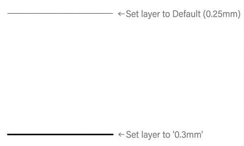
Controlling line thickness is critical for professional CAD drafting. Different lineweights communicate essential manufacturing and architectural details—such as thick lines for section cuts, standard lines for visible outlines, and thin lines for thread crests or centerlines.
If your lines look wrong on-screen or print incorrectly, the fix is usually simple. Here are the four primary methods to change lineweight in AutoCAD, ranked from best practices to advanced plotting techniques.

実は、AutoCAD は標準で JWW 形式に対応していません。
DARE ONE なら、JWW から DWG / DXF への高精度な変換がブラウザ上で今すぐ無料で完了!
拡張子の互換性に悩まず、スムーズに作図作業へ移りましょう。

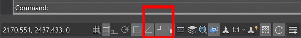
Before you change any settings, make sure AutoCAD is actually displaying line thicknesses on your screen. By default, this feature is often turned off.
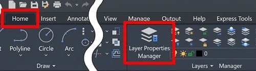
Assigning lineweights by layer is the industry standard. It keeps your drawings organized and ensures consistency across your entire project.
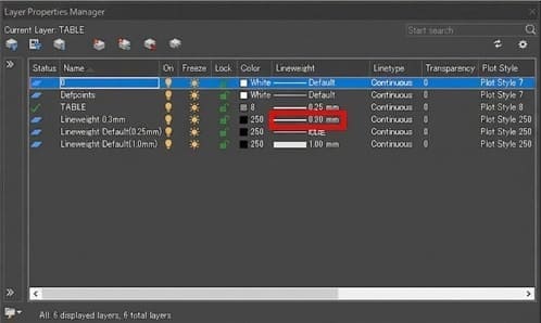
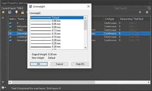
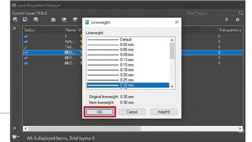
Any object on this layer with its property set to "ByLayer" will now automatically update to the new thickness.
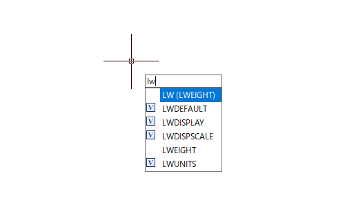
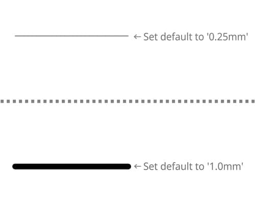
AutoCAD applies a default thickness to all standard lines. If everything looks too thin, you can simply adjust the global default.
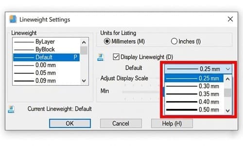
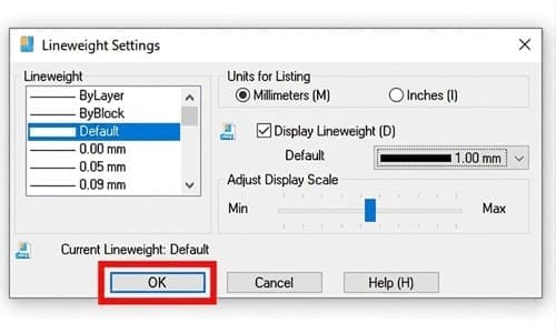
Warning: You can only have one default lineweight per drawing. Changing this will alter the thickness of every layer and object currently set to use the "Default" lineweight.
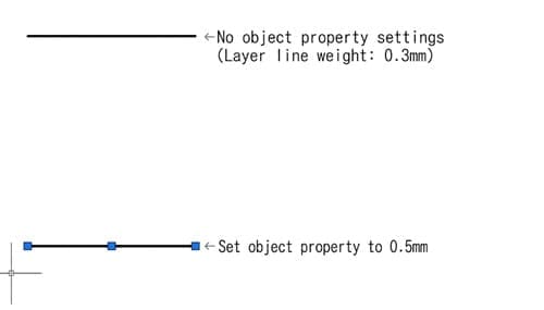
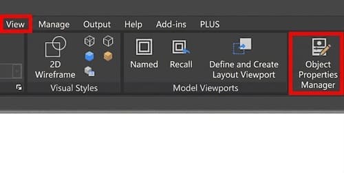
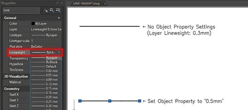
If you need to change the thickness of a single line without affecting the rest of the layer, you can apply a direct override using the Properties palette.

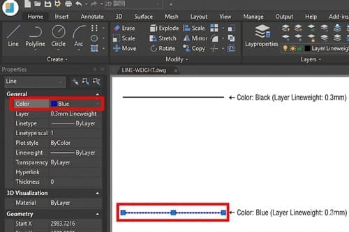
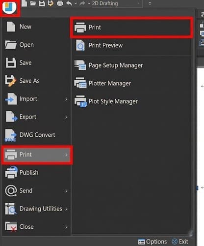
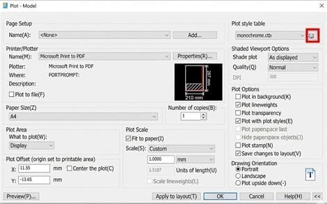
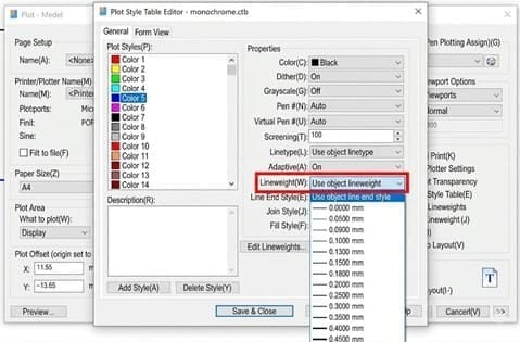
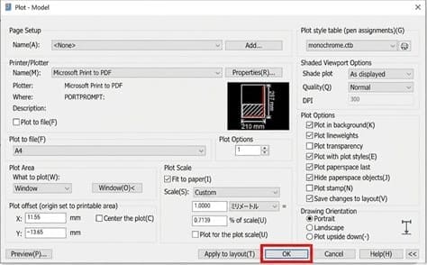
Advanced drafters use Plot Style Tables (CTB or STB) to map specific colors to specific printed lineweights. This allows you to draft with thin, brightly colored lines on a black screen, but print thick, black lines on paper or PDF.
If you have set a lineweight but it isn't showing up correctly, it is likely being overridden by a higher-priority setting. AutoCAD resolves conflicting settings in this exact order:
| Priority | Setting Location | Behavior |
|---|---|---|
| 1 (Highest) | Plot Style Table | Overrides all on-screen properties during printing/PDF export. |
| 2 | Object Properties | Overrides the assigned Layer settings for selected elements. |
| 3 (Lowest) | Layer Properties | The foundational setting. Overridden by Object Properties and Plot Styles. |
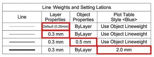
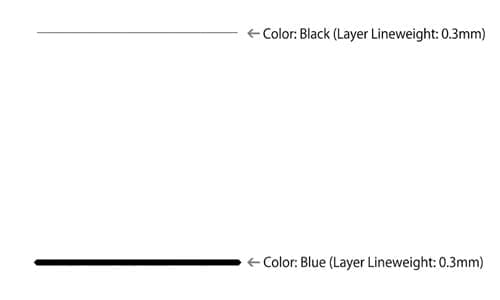
Example: If your Layer is set to 0.3 mm, but you change an Object Property to 0.5 mm, the line will be 0.5 mm. If your Plot Style Table dictates that all blue lines must print at 2.0 mm, that 0.5 mm line will print at 2.0 mm.
If your line thicknesses aren't showing up correctly in your workspace or during the plotting process, check out our comprehensive troubleshooting guide below:
[Reference Article]
■ Lineweights Not Showing in CAD? 5 Settings You Need to Check
Different line thicknesses communicate essential information in technical drawings. In mechanical drafting, for example, specific lineweights are assigned to represent different physical features:
Industry standards (such as ISO or ASME) strictly dictate these line thicknesses to prevent manufacturing errors. Always make sure to follow your company's internal CAD standards and international drafting rules to keep your drawings accurate, readable, and highly professional.
Converting drawings between formats (like DWG, DXF, PDF, or STEP) often results in stripped layers, lost lineweight settings, or garbled text.
If you regularly collaborate with external teams or clients using different CAD standards, DARE makes file conversion effortless. As a cloud-based CAD translation service, DARE accurately converts your 2D and 3D files while preserving your crucial layer hierarchies and property settings—no expensive software licenses required.
Protect your design data and streamline your workflow today. Try DARE’s Free CAD Conversion Tool Now