
Created Date:2024.05.31
Updated Date:2026.03.31
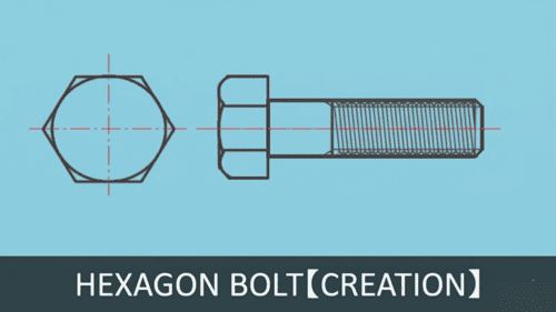 Drawing a standard M20 hex bolt from scratch is a foundational skill for any mechanical drafter or engineer. Whether you are using AutoCAD or a DWG-compatible alternative, mastering the correct sequence of commands—from setting up your layers to applying precise chamfers—will drastically speed up your drafting process.
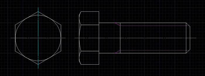
In this guide, we will walk you through the exact steps to draft both the top and side views of an M20 hex bolt, complete with thread details and centerlines.

DARE はブラウザだけで DWG・DXF・JWW・PDF などを相互変換・バージョンダウンができる無料サービスです。
ソフトのインストールも、面倒な待ち時間も不要。今すぐ変換して業務を再開しましょう!

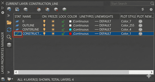
Proper layer management prevents headaches later when you need to hide or modify specific parts of your geometry.
Guidelines: Set the color to Red. (Make this your active layer).
Outline: Set the color to White.
Centerline: Set the color to Cyan.
Adjust Your Grid
Set your Grid and Snap spacing to 2mm for precise manual snapping during this exercise. 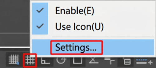
You can access this by right-clicking the Grid Mode icon and selecting Settings.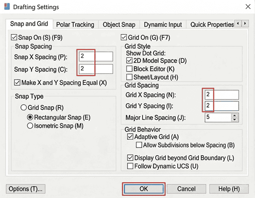
Draw Construction Lines
Use the XLINE (Construction Line) command to create intersecting horizontal and vertical construction lines. 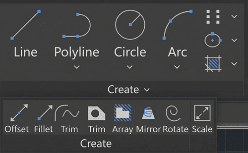
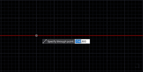
These will serve as the center point for your bolt.
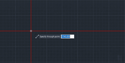
Add an additional vertical line to the right to mark the side view position.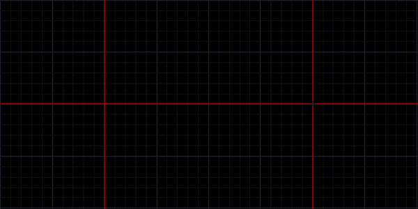
Next, we will draw the top-down view of the bolt head. Switch your active layer to Outline.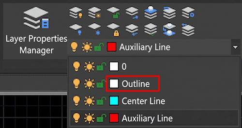
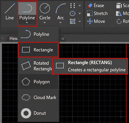
Select the POLYGON command. 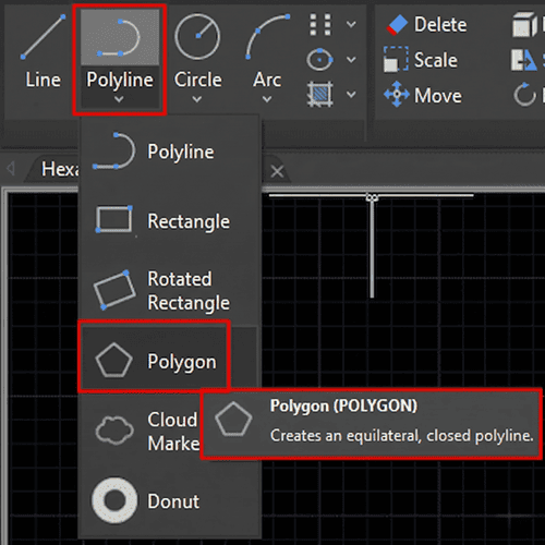
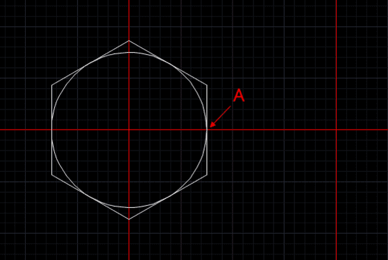
Enter 6 for the number of sides, specify the same center point, and choose Circumscribed about circle. 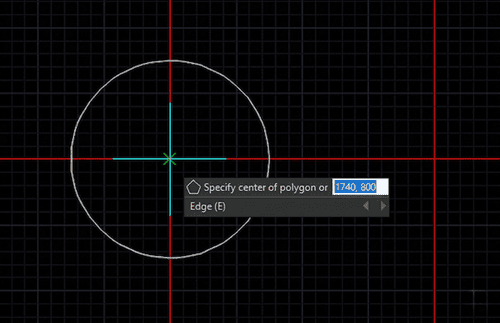
Snap the radius to the right quadrant of your circle.
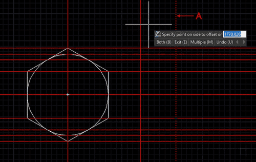
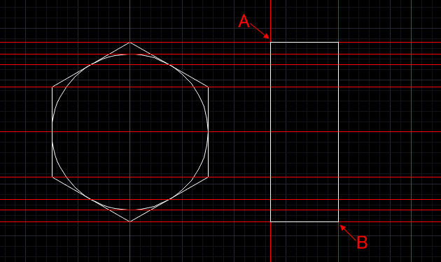
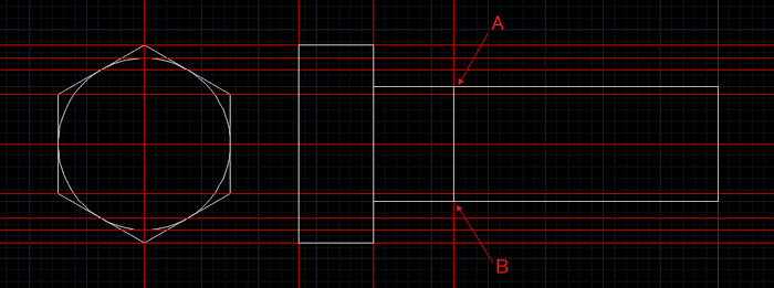
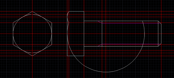
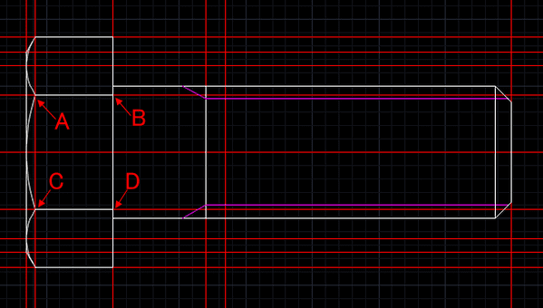
2. Project Guidelines for the Side View
Switch back to your Guidelines layer.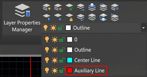
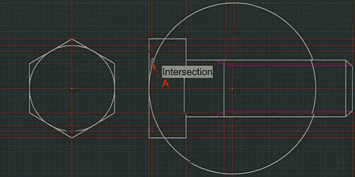
Ensure your End Point and Intersection Object Snaps (OSNAP) are turned on.
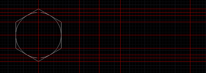
Use the XLINE command to project horizontal lines from the key endpoints and intersections of your hexagon.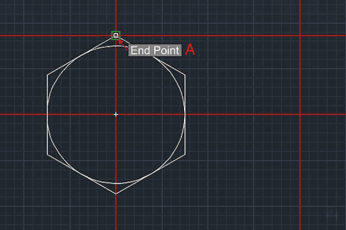
Use the OFFSET command to create vertical boundaries for your side view (e.g., offset by 13mm, 14mm, and 60mm to define the bolt head and shaft lengths).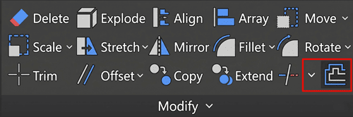
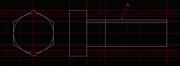
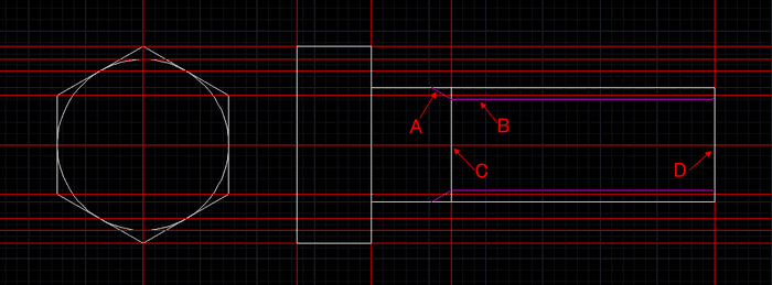
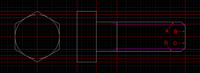
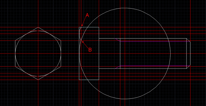
With your guidelines projected, switch your active layer back to Outline to draw the side profile of the bolt body and threads.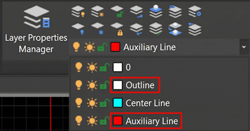
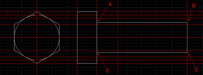
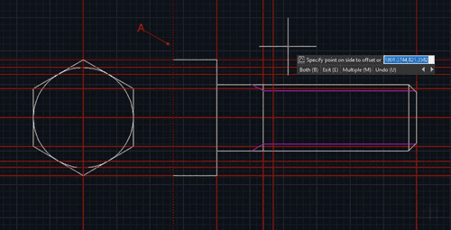
To create the thread, use the OFFSET command to offset the outer shaft line inward by 2mm.
Use the LINE command to draw a 60-degree angled line at the tip of the bolt for the standard thread runout (type 240 degrees in your dynamic input).
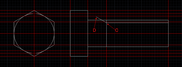
Change the thread line color to Magenta for clarity (optional, but good practice for plotting).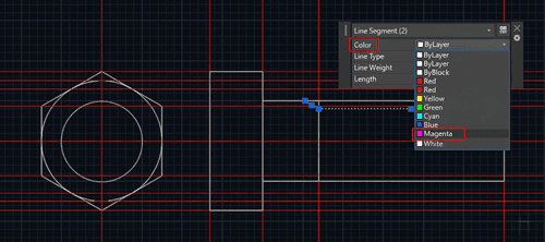
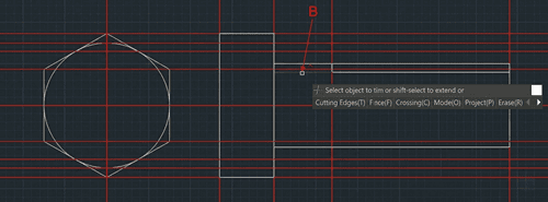
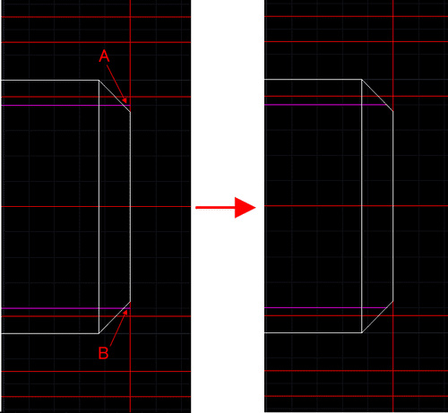
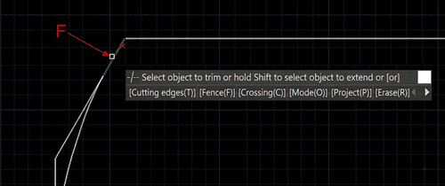
Use the CHAMFER command on the bottom tip of the bolt shaft.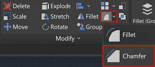
Set your distance to 2.5mm and select the intersecting corner lines.
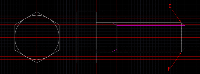
Use TRIM to clean up any overlapping lines.
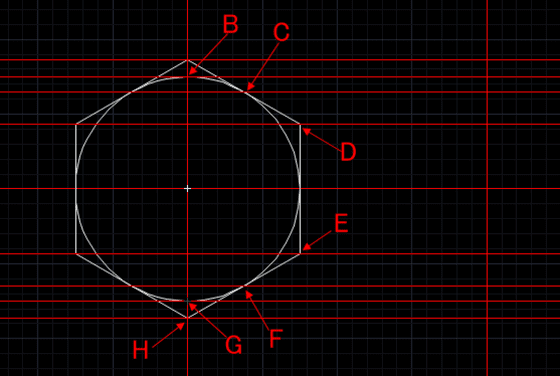
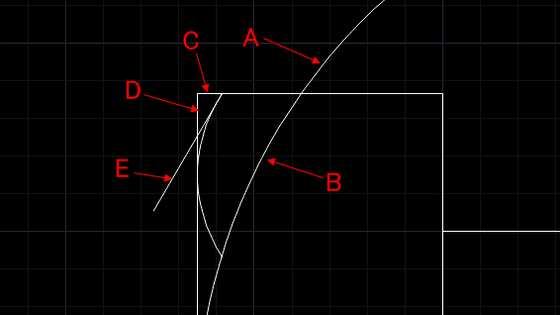
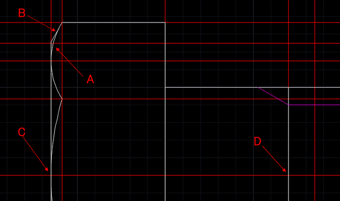
The trickiest part of drawing a hex bolt is accurately representing the curved chamfers on the bolt head.
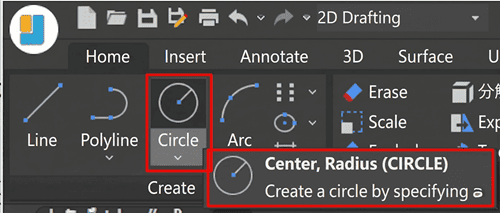
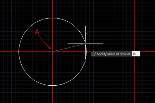
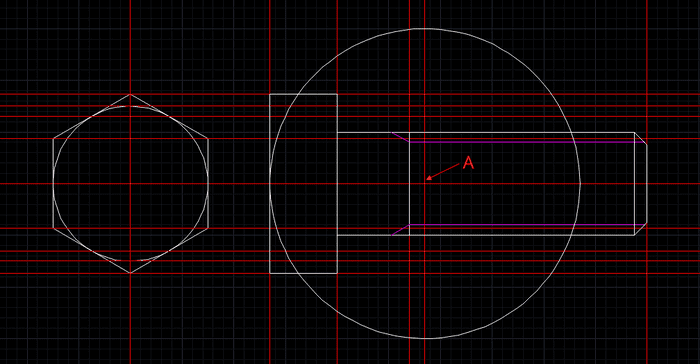
Switch to the Outline layer. Use the CIRCLE command with a 30mm radius from the center top of the bolt head to create the main center arc.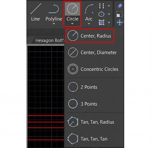
Use the ARC command (Start, End, Radius) to create the smaller side arcs, specifying an 8mm radius.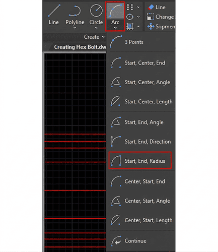
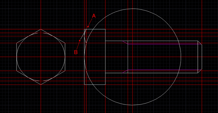
Hide your Guidelines layer temporarily.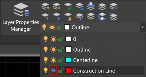
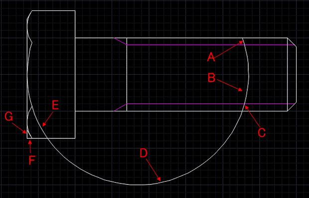
Use TRIM to cut away the excess circle and arc geometry, leaving only the characteristic curved bolt head profile.
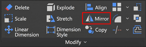
MIRROR these features to the opposite side to ensure perfect symmetry, and trim any remaining excess lines.
To finalize your engineering drawing, you need standard centerlines.
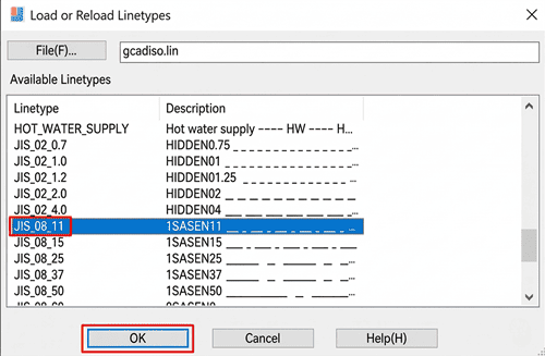
Open your Layer Properties Manager, select your Centerline layer, and click on the linetype.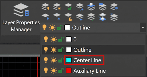
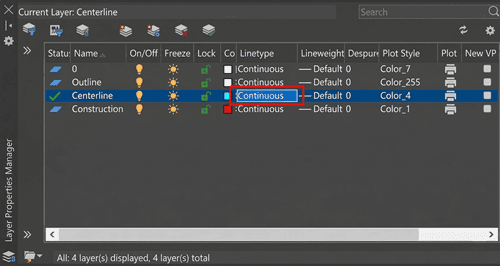
Click Load and select a standard ISO or Center linetype (e.g., CENTER or ISO dash dot).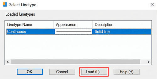
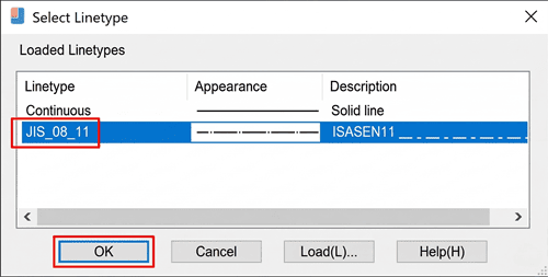
Switch to the Centerline layer and draw lines vertically and horizontally through the exact centers of your top and side views.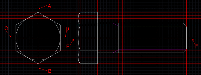
Hide or freeze your Guidelines layer. Save your file as M20_Hex_Bolt.dwg.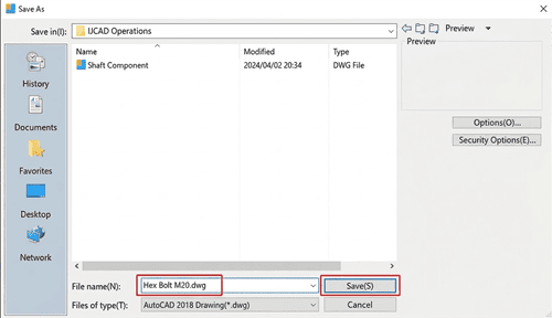
Drawing hardware from scratch is a great exercise, but in a fast-paced engineering environment, you often receive CAD files in formats you can't immediately edit. What happens when a supplier sends you a flat PDF of a mechanical assembly, and you need those parts in your DWG workspace right now?
DARE is the ultimate B2B cloud solution for seamless CAD conversions. Designed for professional engineers and drafters, DARE allows you to:
Accurately convert PDF to DWG/DXF while retaining crisp vector layers and geometry.
Instantly batch-convert files entirely in the cloud—no heavy software installations required.
Eliminate the tedious process of redrawing standard parts, allowing you to focus on actual design work.
Stop wasting valuable engineering hours redrawing flat PDFs. Try DARE for free today and streamline your design pipeline!